Motion radar: movement direction in polar form
Objectives
Section titled “Objectives”- Turn accelerometer and gyroscope readings into angle and magnitude and draw them in polar form
- Use a baseline and a dead-band to drop small jitter before drawing, and work out how much lag a moving average would add at the 50 ms read period
- Design a view that lets a user read the direction within a second
Concepts
Section titled “Concepts”The baseline is a “resting pose” captured once at boot, not a running high-pass filter
Section titled “The baseline is a “resting pose” captured once at boot, not a running high-pass filter”radar_update_baseline() averages accel X/Y and gyro Z over the first 30 samples (at the
BMI270_SAMPLE_PERIOD_MS = 50 read period, that is roughly the first 1.5 seconds after boot), stores them as
s_baseline_acc_x/y and s_baseline_gyr_z, and never recomputes them again for the rest of the session. This
is the simplest way to remove a constant gravity/offset (baseline subtraction), not a continuously running
moving-average or low-pass filter — the upside is zero added latency; the downside is that if the pose at boot is
not the pose you actually use, the baseline stays wrong for the whole session.
The radar’s angle and magnitude come from the difference from baseline, not the raw three axes
Section titled “The radar’s angle and magnitude come from the difference from baseline, not the raw three axes”Unlike a textbook Cartesian-to-polar formula, the code computes acc_dx = sample.acc_g_x - s_baseline_acc_x and
acc_dy the same way, then acc_xy_delta_g = sqrt(acc_dx² + acc_dy²) — using only the X/Y axes of the
difference, never the Z axis, and never the raw vector’s magnitude (which would always include roughly 1g of
gravity even when the board is not moving). The direction is atan2f(acc_dy, acc_dx) of this difference vector —
in other words, the radar points toward “the direction acceleration just changed from what it was at boot,” not
“the direction the total acceleration vector currently points.”
Two dead-band thresholds gate whether the needle moves at all
Section titled “Two dead-band thresholds gate whether the needle moves at all”Before even computing an angle, the code checks whether acc_xy_delta_g >= 0.06g or
gyr_z_delta_abs_dps >= 12°/s. If neither holds, motion_active = false, the angle is forced to 0, and no
needle is drawn at all. The reason: atan2() of a near-zero vector (mg-level noise) returns a nearly random
angle, so without this dead-band the needle would wander even while the board sits perfectly still. Unlike a
low-pass filter, this technique adds no latency — there is no averaging across time, just a per-sample
decision on whether to show or hide.
Three intensity levels come from a normalized score comparing both axes
Section titled “Three intensity levels come from a normalized score comparing both axes”radar_calc_motion_level() converts acc_xy_delta_g and gyr_z_delta_abs_dps into a score by dividing each by
its own constant (0.45g and 140°/s), then picks whichever score is larger to decide the level —
< 0.35 is LOW (green 0x22C55E), 0.35–0.80 is MEDIUM (amber 0xF59E0B), ≥ 0.80 is HIGH (red 0xEF4444).
This system does not appear in the upstream README at all, but it is what lets a user read both “how hard” (from
color) and “which way” (from the needle’s angle) in a single glance.
The real screen uses an lv_scale widget with one needle, not a canvas with rings and trace history
Section titled “The real screen uses an lv_scale widget with one needle, not a canvas with rings and trace history”The upstream README describes an lv_canvas drawing four concentric rings, N/E/S/W cardinal lines, and a
64-point trace history connected into a fading line. The real code instead uses lv_scale, LVGL 9’s
ready-made widget (a round 0–360° dial with 41 ticks), and draws one needle with
lv_scale_set_line_needle_value(scale, needle, needle_len, angle_i), where the needle’s length encodes movement
magnitude, its angle encodes direction, and it is hidden (LV_OBJ_FLAG_HIDDEN) whenever motion_active is
false. There is no trace history or multi-ring grid at all. The gyro reading is shown through a separate dual-ring
arc gauge (intensity_gyr_arc) that maps the delta to 0–100, not an arc drawn at the Z-axis angle as the upstream
README describes.
Worked example
Section titled “Worked example”This episode’s code lives on the Developer Hub (pinned to commit 9a8e3ed) — read the Why section of the
upstream README
to understand its purpose, but the excerpts below are copied from the actual files (Apache-2.0,
tesaiot/developer-hub, same commit), because the math and the on-screen widget differ substantially from what the
upstream README describes.
app_ui/radar/radar_presenter.c — angle and dead-band from the baseline delta:
acc_dx = sample.acc_g_x - s_baseline_acc_x;acc_dy = sample.acc_g_y - s_baseline_acc_y;acc_xy_delta_g = sqrtf((acc_dx * acc_dx) + (acc_dy * acc_dy));gyr_z_delta_abs_dps = fabsf(sample.gyr_dps_z - s_baseline_gyr_z);
/* Treat signal as STILL until delta crosses threshold from baseline. */motion_active = s_baseline_ready &&                ((acc_xy_delta_g >= RADAR_STILL_ACC_DELTA_G) ||                 (gyr_z_delta_abs_dps >= RADAR_STILL_GYR_DELTA_DPS));
angle_deg = motion_active ? (atan2f(acc_dy, acc_dx) * RADAR_DEG_PER_RAD) : 0.0f;level = motion_active ? radar_calc_motion_level(acc_xy_delta_g, gyr_z_delta_abs_dps) : RADAR_LEVEL_LOW;
The three intensity levels from a normalized score:
static radar_motion_level_t radar_calc_motion_level(float acc_xy_delta_g, float gyr_z_delta_abs_dps){    float acc_score = acc_xy_delta_g / 0.45f;    float gyr_score = gyr_z_delta_abs_dps / 140.0f;    float score = (acc_score > gyr_score) ? acc_score : gyr_score;
    if (score < 0.35f) { return RADAR_LEVEL_LOW; }    if (score < 0.80f) { return RADAR_LEVEL_MEDIUM; }    return RADAR_LEVEL_HIGH;}
app_ui/radar/radar_view.c — one needle on an lv_scale, hidden while still:
s_view.radar_scale = lv_scale_create(radar_card);lv_scale_set_mode(s_view.radar_scale, LV_SCALE_MODE_ROUND_INNER);lv_scale_set_range(s_view.radar_scale, 0, 360);lv_scale_set_total_tick_count(s_view.radar_scale, 41);
s_view.radar_needle = lv_line_create(s_view.radar_scale);lv_scale_set_line_needle_value(s_view.radar_scale, s_view.radar_needle, 18, 0);/* Hide needle in STILL state; presenter shows it only when motion is active. */lv_obj_add_flag(s_view.radar_needle, LV_OBJ_FLAG_HIDDEN);main_example.chands the I2C handle toradar_presenter_start(), exactly as the upstream README describesapp_sensor/bmi270/bmi270_config.h—BMI270_SAMPLE_PERIOD_MS = 50(faster than lesson 3.2’s 200 ms, since a radar needs higher responsiveness)- See the full folder at
int_ep05_bmi270_radar_view/
Common mistakes
Section titled “Common mistakes”- The board is not level at boot, so the needle sticks pointing one way even when still — the baseline is captured once from the first 30 samples; if the board was tilted at boot, a later level pose will differ from the baseline enough to look like continuous motion. Hold the board still in its intended pose when powering on.
- Assuming magnitude comes from all three axes (x, y, z) — the real code only uses the X/Y difference from baseline, never Z, and never the raw value.
- Removing or shrinking the dead-band to make it “more responsive” — this makes the needle wander randomly
while the board sits perfectly still, because
atan2()of a near-zero vector is meaningless. - Assuming there is a canvas with 4 rings and a 64-point trace — the real screen uses a ready-made
lv_scalewidget with a single needle; no movement history is kept at all.
Build and flash
Section titled “Build and flash”# In the master template folder (see lesson 1.1)# 1) Delete the old episode's files in proj_cm55/apps/# 2) Copy all of this episode's files into proj_cm55/apps/make buildmake program # flash through KitProg3Or open this example on the Developer Hub and flash the ready-made firmware.
See it work first
Section titled “See it work first”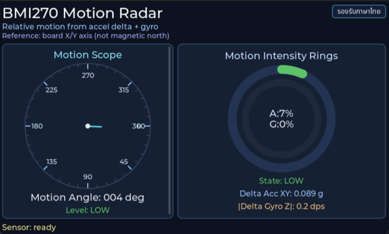
Before reading the code, guess what objects this screen has, and what changes when the user taps it or when a sensor value changes.
Try a change
Section titled “Try a change”- Guess before you change anything: pick one value the example’s README explains in the How section, and write down what you expect to change on the screen or in the log.
- Change and run: build + flash, then compare against your guess. If it does not match, find which part you misunderstood.
- Extend: add one thing the example does not yet have, and keep a photo or video in your portfolio.
Check your understanding
Section titled “Check your understanding”- What does atan2 do when finding the direction?
- How does a dead-band differ from a moving average in terms of the lag of the point on the radar?
- What should the point’s colour or size communicate?
The answers are in the example’s README and in the code. If you cannot answer one, go back and read the Why / What / How section again.
References
Section titled “References”- Episode README · code folder · commit
9a8e3ed - Open this example on the Developer Hub
- The code belongs to the Developer Hub and is referenced by link, not copied into this repository
Review questions
Answer on your own first, then open the answer.
-
What does the needle angle on this example's radar represent? (Objective 1)
- ทิศของการเปลี่ยนแปลงความเร่งในระนาบ X/Y เทียบกับ baseline ตอนเริ่ม คำนวณด้วย atan2(dy, dx) และความยาวเข็มตามขนาดของการเปลี่ยนแปลง
- ทิศเหนือแม่เหล็ก
- มุมที่บอร์ดหมุนสะสมจาก gyroscope
- มุมเอียงสัมบูรณ์เทียบกับแรงโน้มถ่วง
Show answer
Answer: A. ทิศของการเปลี่ยนแปลงความเร่งในระนาบ X/Y เทียบกับ baseline ตอนเริ่ม คำนวณด้วย atan2(dy, dx) และความยาวเข็มตามขนาดของการเปลี่ยนแปลง
radar_poll_sensor_cb() หา acc_dx = acc_g_x − baseline_x และ acc_dy แบบเดียวกัน แล้วใช้ atan2f(acc_dy, acc_dx) เป็นมุม ส่วน needle_len ใน view คำนวณจาก acc_xy_delta_g จึงเป็นเวกเตอร์ของการเปลี่ยนแปลง ไม่ใช่เข็มทิศและไม่ใช่มุมที่สะสมจาก gyro
-
You power on while holding the board tilted, then lay it flat and still on the table. What does the radar show? (Objective 1)
- STILL เพราะบอร์ดไม่ขยับ
- เข็มค้างชี้ทิศหนึ่งแม้บอร์ดนิ่ง เพราะ baseline จาก 30 ตัวอย่างแรก (ราว 1.5 วินาที) ถูกจับตอนเอียง ท่าราบจึงต่างจาก baseline เกินเกณฑ์ STILL
- radar ตั้ง baseline ใหม่เองเมื่อบอร์ดนิ่ง
- จอขึ้น error เพราะ baseline ไม่ถูกต้อง
Show answer
Answer: B. เข็มค้างชี้ทิศหนึ่งแม้บอร์ดนิ่ง เพราะ baseline จาก 30 ตัวอย่างแรก (ราว 1.5 วินาที) ถูกจับตอนเอียง ท่าราบจึงต่างจาก baseline เกินเกณฑ์ STILL
radar_update_baseline() เฉลี่ย RADAR_BASELINE_SAMPLES = 30 ตัวอย่างแรกที่ 50 ms ต่อตัวอย่าง แล้วไม่คำนวณใหม่อีก การเปลี่ยนท่าทางถาวรจึงดูเหมือนการเคลื่อนไหวตลอดเวลา ควรวางบอร์ดนิ่งในท่าใช้งานตอนเปิดเครื่อง หรือเพิ่มปุ่มตั้ง baseline ใหม่
-
Why does the code treat the board as STILL until the change from baseline exceeds 0.06 g or 12 °/s? (Objective 2)
- เพื่อให้วาดจอได้เร็วขึ้น
- เพราะ BMI270 วัดค่าที่ต่ำกว่านั้นไม่ได้
- เพื่อประหยัดพลังงานของเซนเซอร์
- เป็น dead-band กันสัญญาณรบกวนเล็ก ๆ รอบ baseline: atan2 ของเวกเตอร์ที่เล็กมากให้มุมสุ่มไปทุกทิศ เข็มจะส่ายทั้งที่บอร์ดนิ่ง แลกกับการไม่เห็นการเคลื่อนไหวที่เล็กกว่าเกณฑ์
Show answer
Answer: D. เป็น dead-band กันสัญญาณรบกวนเล็ก ๆ รอบ baseline: atan2 ของเวกเตอร์ที่เล็กมากให้มุมสุ่มไปทุกทิศ เข็มจะส่ายทั้งที่บอร์ดนิ่ง แลกกับการไม่เห็นการเคลื่อนไหวที่เล็กกว่าเกณฑ์
motion_active เป็นจริงเมื่อ acc_xy_delta_g ≥ RADAR_STILL_ACC_DELTA_G หรือ gyr_z_delta ≥ RADAR_STILL_GYR_DELTA_DPS ถ้าไม่มีเกณฑ์นี้ noise ระดับ mg จะทำให้มุมกระโดด เพราะทิศของเวกเตอร์ที่เกือบเป็นศูนย์ไม่มีความหมาย ตัวอย่างนี้ใช้ dead-band แทนการกรองแบบ low-pass จึงไม่เพิ่มความหน่วง
-
If you add an 8-sample moving average to acc_dx and acc_dy polled every 50 ms, the picture steadies, but by roughly how much does the average delay grow? (Objective 2)
- ไม่เพิ่ม เพราะการเฉลี่ยคำนวณเสร็จในรอบเดียว
- ราว 25 ms
- ราว 175 ms
- ราว 400 ms
Show answer
Answer: C. ราว 175 ms
ค่าเฉลี่ยเคลื่อนที่ N ตัวอย่างหน่วงราว (N − 1) / 2 ตัวอย่าง = 3.5 × 50 ms ≈ 175 ms และต้องรอเต็มหน้าต่าง 400 ms กว่าจะตามการเปลี่ยนแบบขั้นบันไดได้ครบ ยิ่งกรองแรง จุดยิ่งนิ่งแต่ตามการเคลื่อนไหวช้าลง ความหน่วงนี้มาจากการที่ผลลัพธ์รวมตัวอย่างในอดีต ไม่ได้มาจากเวลาคำนวณ
-
One sample gives acc_xy_delta = 0.20 g and gyr_z_delta = 30 °/s. Which level and colour are shown? (Objective 3)
- LOW สีเขียว
- MEDIUM สีเหลืองอำพัน
- HIGH สีแดง
- STILL สีเทา
Show answer
Answer: B. MEDIUM สีเหลืองอำพัน
radar_calc_motion_level() ใช้คะแนนที่มากกว่าระหว่าง 0.20 / 0.45 ≈ 0.44 กับ 30 / 140 ≈ 0.21 ได้ 0.44 ซึ่ง ≥ 0.35 แต่ < 0.80 จึงเป็น MEDIUM (0xF59E0B) การใช้สีบอกว่าแรงแค่ไหน และใช้มุมเข็มบอกว่าไปทางไหน ทำให้ผู้ดูอ่านได้ทั้งสองเรื่องในแวบเดียว
Cite this lesson
If you teach from this lesson or reuse it in slides or documents, credit it with the text below. If you changed it, add (adapted) after the title.
"Motion radar: movement direction in polar form" from TESA Open Knowledge by the Thai Embedded Systems Association (TESA), https://github.com/tesaiot/tesa-qualification-program, licensed under CC BY-NC 4.0
Thai attribution: "Motion radar: วาดทิศการเคลื่อนไหวแบบ polar" จาก TESA Open Knowledge โดยสมาคมสมองกลฝังตัวไทย (Thai Embedded Systems Association: TESA) https://github.com/tesaiot/tesa-qualification-program สัญญาอนุญาต CC BY-NC 4.0
This lesson adapts the source below; keep its credit too.
https://github.com/tesaiot/developer-hub/blob/9a8e3ed1d813bfd67fabf6b7ac15c6ff9750b465/int_ep05_bmi270_radar_view · Code stays in the Developer Hub and is linked at pinned commits, never copied: the episodes, practice codes and main-branch examples are Apache-2.0; the master template and the OPTIGA client carry Infineon/Cypress EULAs.
TESA Open Knowledge · © 2026 สมาคมสมองกลฝังตัวไทย (TESA) · CC BY-NC 4.0
Content is licensed CC BY-NC 4.0. Reuse it non-commercially and credit the Thai Embedded Systems Association (TESA) every time. · How to cite TESA